STUSB4500 SW drivers and tools (USB-C Power Delivery)
Autonomous USB-C PD controller for Power Sinks / UFP (i.e. on the device’s side)
Simple solution for barrel connector replacement, by using instead a universal USB connector.
Certified by USB-IF consortium for USB Type-C and USB Power Delivery applications (USB-C & USB PD).
Application summary
By default, a USB Type-C port on your hardware can get only 5V from a USB-PD Power Source (Host / DFP)
This product enables to automatically negotiate a higher voltage from the source (>5V) up to 100W (20V@5A).
For instance, if the power brick can provide 4 power profiles (5V, 9V, 15V and 20V), then the STUSB4500 will request the highest voltage available (20V).
Another example, if the power brick can provide 4 power profiles (5V, 9V, 15V and 20V) but the Application needs 9V to boot, then the STUSB4500 can be programmed to always request 9V.
This part can be easily implemented in a battery charger with USB-C input in the application.
The device doesn’t need any software to run (it is autonomous), but it is possible to connect to this device by I2C to take control over the default device behavior, or to get the power information (Voltage/Current) of the attached power source at the other side of the cable. This is what is shown in the demo source code of the project’s repository (stusb4500_firmware_src).
Info:
- Device: STUSB4500 USB Type-C & USB PD controller
- Manufacturer: STMicroelectronics
- Typical Application: To get automatically higher power on Vbus at the insertion of USB-C cable.
- USB power role: Power SINK
-
USB data role: Independent (works with no data, or with UFP (USB Device) that can be USB2.0 or USB3.1)
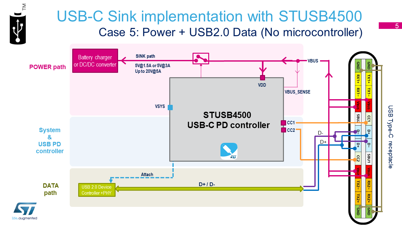
Note: If using the USB-C connector for both Power and Data (with STUSB4500 controller for Power communication on one side, and a USB Data controller on the other side), then the USB-C specification requires for a Power Sink application, that its initial data role (at cable attachment) is always UFP (Device).
Similarly, the initial data role of a Power Source application is always DFP (Host).
To change the role, it is needed to send a USB PD command:PowerRole_SwaporDataRole_Swap. (command not supported by STUSB4500) - Features: Autonomous, configurable, easy to use, small footprint
- Operating supply: 5V to 20V directly from Vbus of the USB-C cable.
Or a lower power (3.3V) for battery supplied applications - Power Consumption: 140 uA only
- Package: QFN-24 (Quad-Flat No-leads), WLCSP (Wafer Level Chip Scale Package)
- Part number: STUSB4500QTR, STUSB4500BJR
- USB Spec: USB Type-C v1.2 , USB PD v2.0 & v3.0
Presentation
The STUSB4500 is a USB Power Delivery controller (USB PD) that addresses sink devices. It implements a proprietary algorithm to allow the negotiation of a power delivery contract with a USB PD source without MCU support (auto-run mode). PDO profiles are configured in an integrated non-volatile memory (NVM).
The device supports dead battery mode and is suited for sink devices powered from dead battery state and requiring high power charging profile to be fully operational.
Thanks to its 20 V technology, it implements high voltage features to protect the CC pins against short-circuits to VBUS up to 22 V and to support high voltage on the VBUS pins directly connected to the VBUS power path up to 28 V.
Key Features
- Auto-run USB Type-C™ and USB PD sink controller
- Dead battery mode support
- Up to 3 sink PDO configurable profiles
- Dual high power charging path support
- Integrated VBUS switch gate drivers (PMOS)
- Integrated VBUS voltage monitoring
- Internal and/or external VBUS discharge paths
- Short-to-VBUS protections on CC pins (22 V)
- High voltage capability on VBUS pins (28 V)
- Dual power supply (VSYS and/or VDD):
- VDD = [4.1 V; 22 V]
- or VSYS = [3.0 V; 5.5 V]
- Debug accessory mode support
- Temperature range: -40 °C up to 105 °C
- ESD: 3 kV HBM - 1.5 kV CDM
- Certified:
- USB Type-C™ rev 1.2
- USB PD rev 2.0 (Official Test ID: TID #1000133)
- Interoperable with USB PD rev 3.0
Programming
Register Programming
The USB-PD chip has 148 programmable registers (0x94).
To simplify the implementation, Use the firmware example contained in this repository (STSW-STUSB003 Software library for STUSB4500) to control the STUSB4500 with a Micro-controller, and take control over the default behavior of the device.
You can for instance with the MCU request any PDO that you want from the DFP (you are no more limited to 3 PDOs).
Link: Source code for this project
Additional information: Firmware readme
NVM programming
The chip can be used in standalone with a custom configuration thanks to its internal memory.
The Non-Volatile Memory (NVM) contains the STUSB4500 configuration which load automatically at power-up.
But the NVM memory is not directly accessible byte per byte. It has to be accessed by block, following a specific sequence.
The NVM size is 40 bytes.
The NVM programming is done through I2C.
You can program the chip during manufacturing flow with any standard programming tool, as long as the tool has access to the I2C interface.
Link: Source code for this project
Here are the steps to program the NVM memory (with your own tools):
- Use the STSW-STUSB002 GUI to configure the STUSB4500 parameters according to your application needs (PDO, Voltage, Current, Overvoltage protection, …).
Note that the GUI can be used offline for the parameters selection (i.e. without being connected physically to STUSB4500). - With the GUI, generate the NVM config file (.h) (or .txt) which contains the binary configuration of STUSB45
- Use the NVM_Library source code (which contains the specific I2C sequence) to create an application which writes the binary configuration (.h) into the chip NVM memory
- Reset the chip so that it reloads its latest NVM configuration
- Now the chip is programmed. Each time it starts up, it will load the configuration from the NVM memory.
- Note 1 : In a typical application, the chip’s NVM only needs to be programmed once (during manufacturing flow).
- Note 2 : The NVM technology has a limited number of write cycles possible (few thousands). So do not use an application which re-write the NVM all the time.
Here is a Faster alternative to program the NVM memory (with the GUI and Nucleo board):
- Connect the STUSB4500 eval board on top of STM32F072 Nucleo board. And connect the Nucleo board to your computer via USB.
- Use the STSW-STUSB002 GUI to configure the STUSB4500 parameters according to your application needs (PDO, Voltage, Current, Overvoltage protection, …).
- With the GUI, click the “Write NVM” button to flash the memory
- Reset the chip so that it reloads its latest NVM configuration
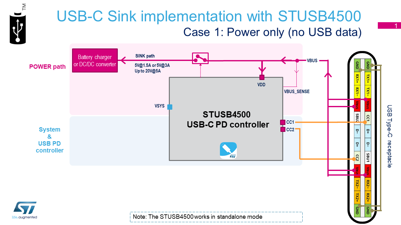
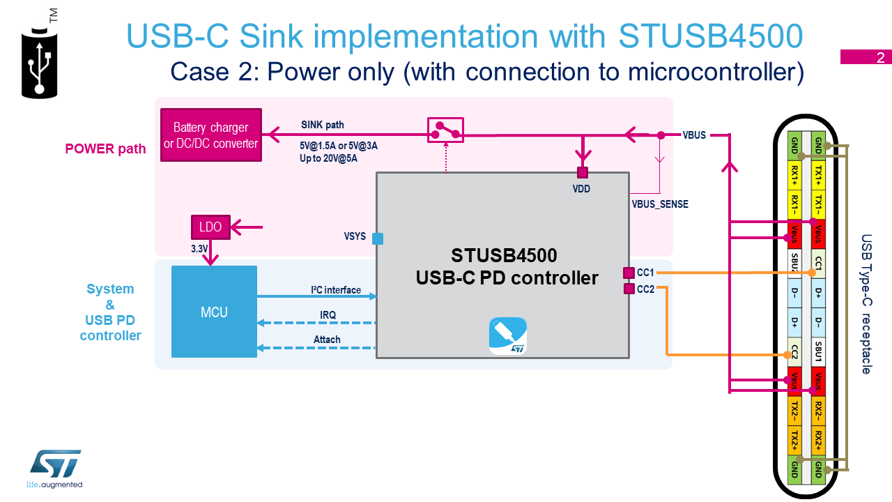
Block Diagram
- Power only
- Case 1: Power (5V to 20V)
- Case 2: Power (5V to 20V) with Microcontroller
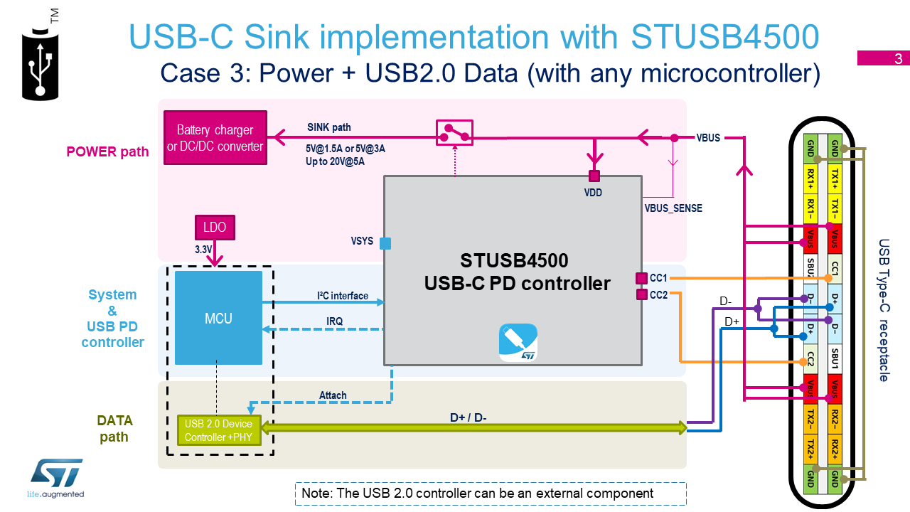
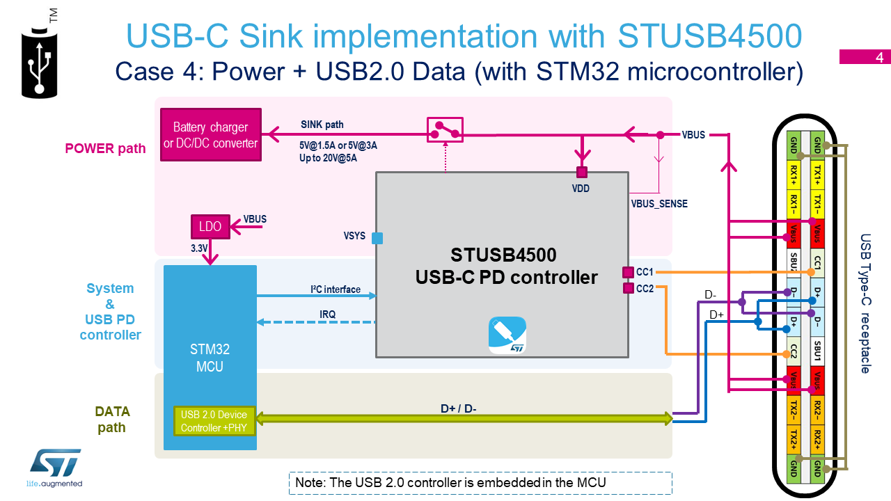
- Power + Data
- Case 3: Power (5V to 20V) + Data (USB 2.0) with Microcontroller & external USB2 controller
- Case 4: Power (5V to 20V) + Data (USB 2.0 FullSpeed) with STM32 Microcontroller
- Power + Data
- Case 5: Power (5V to 20V) + Data (USB 2.0) [without Microcontroller]
- Power + SuperSpeed Data
- Case 6: Power (5V to 20V) + Data (USB 3.1) with Microcontroller & external USB3 controller PHY
For USB3.0, USB3.1 and USB3.2 data speed, connect the SuperSpeed lines: SSTX+/- and SSRX+/-
- Case 6: Power (5V to 20V) + Data (USB 3.1) with Microcontroller & external USB3 controller PHY
Evaluation Boards
There are different boards available to test the product.
-
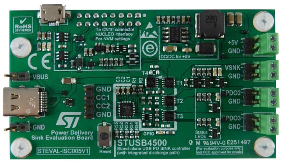
STUSB4500 evaluation board : STEVAL-ISC005V1
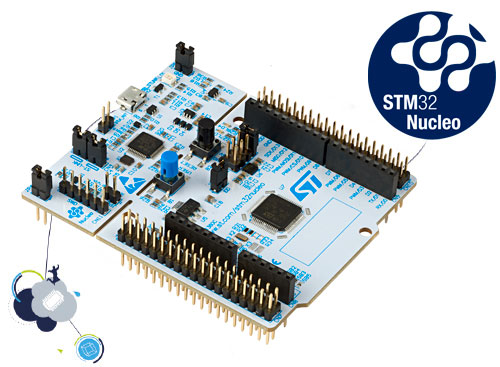
https://www.st.com/content/st_com/en/products/evaluation-tools/solution-evaluation-tools/psu-and-converter-solution-eval-boards/steval-isc005v1.html- Note : To use the GUI for configuration, This board requires to be connected on top of a STM32 Nucleo board : NUCLEO-F072RB or NUCLEO-G071RB
https://www.st.com/en/evaluation-tools/nucleo-f072rb.html
https://www.st.com/en/evaluation-tools/nucleo-g071rb.html
Before using the GUI with these boards, flash the STM32 with the corresponding binary file.
- Note : To use the GUI for configuration, This board requires to be connected on top of a STM32 Nucleo board : NUCLEO-F072RB or NUCLEO-G071RB
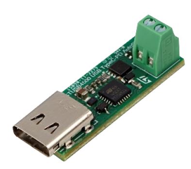
- STUSB4500 mini eval-board : EVAL-SCS001V1
https://www.st.com/content/st_com/en/products/evaluation-tools/solution-evaluation-tools/psu-and-converter-solution-eval-boards/eval-scs001v1.html
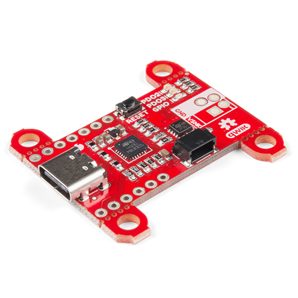
- SparkFun Power Delivery Board - USB-C (Qwiic)
https://www.sparkfun.com/products/15801
https://learn.sparkfun.com/tutorials/power-delivery-board—usb-c-qwiic-hookup-guide
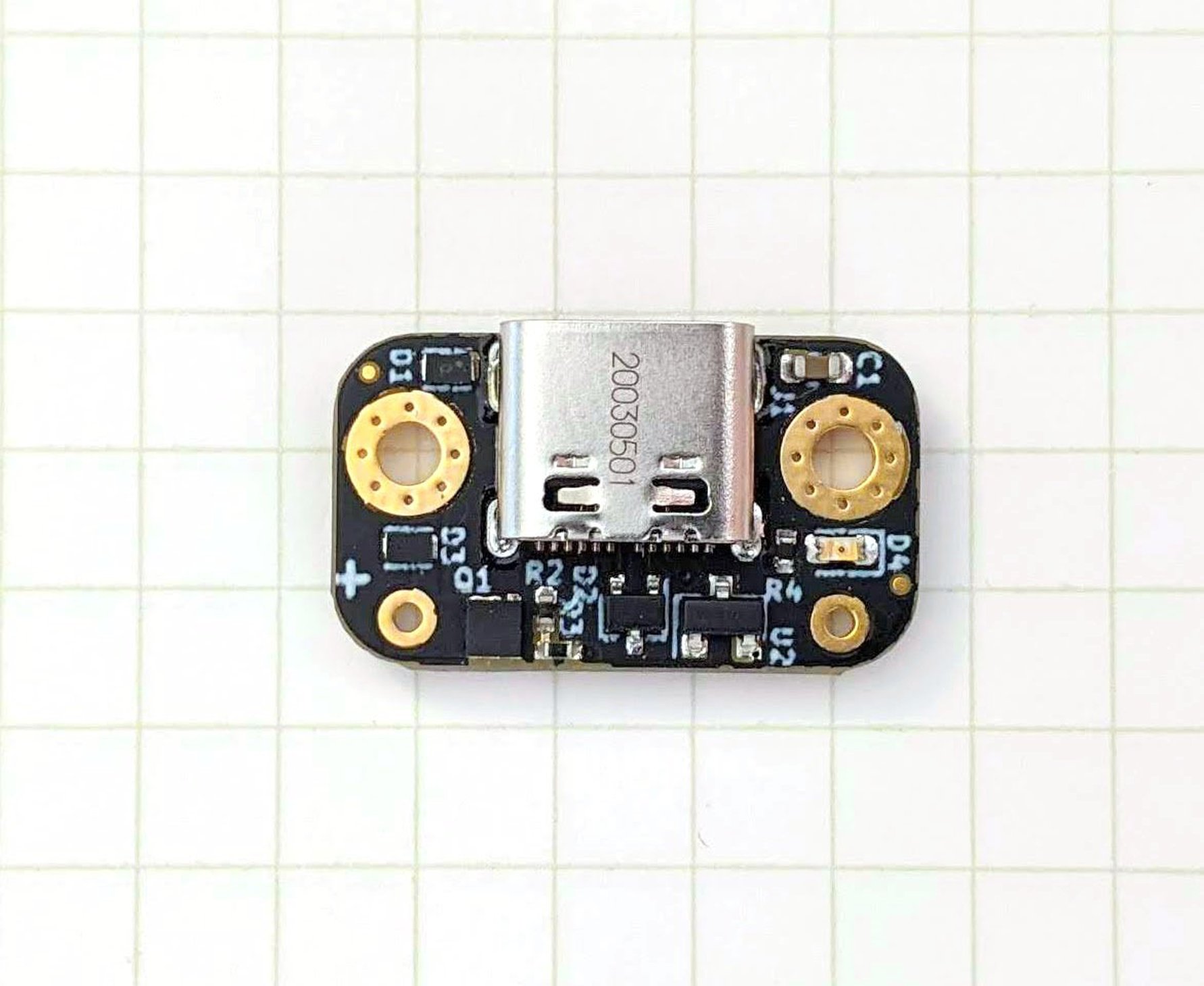
- Tindie fpx: easy USB-C power for all your devices
https://www.tindie.com/products/oxplot/fpx-easy-usb-c-power-for-all-your-devices/
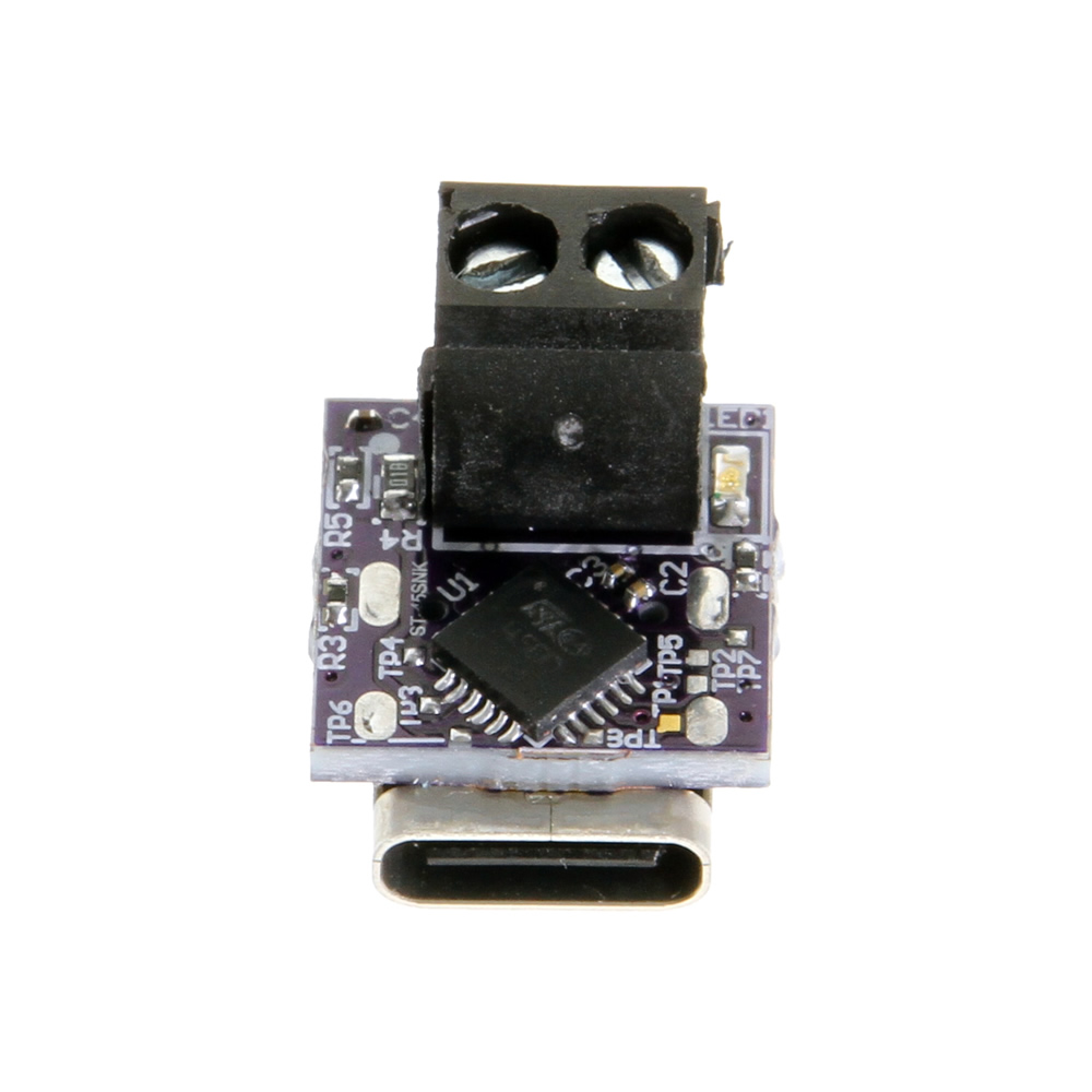
- Nano USB PD to DC Module : CG-NANOPDDC
https://www.coolgear.com/product/nano-usb-pd-to-dc-module-pd-negotiation-device
More


Notes
The STUSB4500 is a standalone USB-C PD controller for UFP only (Power SINK).
Its counter part for DFP only (Power SOURCE) is STUSB47.
Because these 2 devices have been certified by USB-IF, it means they are interoperable with any USB-C PD application on the market.
Plenty of scenarios are possible, for instance:
| Source ctrl | USB-C cable | Sink ctrl |
|---|---|---|
| STUSB47x0 | <———-> | STUSB4500 |
| STUSB1600 | <———-> | STUSB4500 |
| STUSB1700 | <———-> | STUSB4500 |
| STUSB1602 + STM32Fx | <———-> | STUSB4500 |
| STUSB1702 + SPC58 | <———-> | STUSB4500 |
| STM32G0xx | <———-> | STUSB4500 |
| STUSB47x0 | <———-> | STM32Fx + STUSB4500 |
| STUSB47x0 | <———-> | STM32MP1 + STUSB4500 |
| STM32MP1 + STUSB1600 | <———-> | STUSB4500 |
| Any USB-C Source | <———-> | STUSB4500 |
| Any USB PD Source | <———-> | STUSB4500 |